Cut Bodies
![]()
The Cut Bodies function allows you to cut one or several solid or sheet bodies with selected elements.
![]() Note:
Note:
- You may use a large number of entities, such as wireframe elements, points, faces and edges for cutting.
Access
- Activate the Solids tab and then click the
 icon in the Operations section of the ribbon.
This opens the Cut Bodies - Options tab which is displayed along with the ribbon containing the Selection, Filters, Options and General sections.
Procedure
- Using the Object selection filters, select one or several bodies which you want to cut.
- Using the Environments filter, select the type of cutting element that you want to use.
- Using the appropriate entity filter, select the cutting element(s) to use.
- Using the Direction selection options, define the cutting direction and Right Mouse click to confirm.
- The options available in this dialog box depend on the selected cutting entities.
Select the required options according to the result that you want to achieve. - Validate, either by a Right Mouse click or by clicking the
 icon in the graphic area or in the function dialog box.
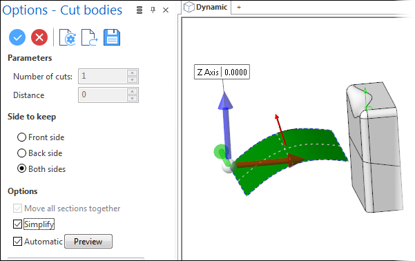
If ![]() Options has been activated in the ribbon, the Options - Cut bodies dialog box is displayed along with the slider in the graphic area allowing you to move the cut to another location.
Options has been activated in the ribbon, the Options - Cut bodies dialog box is displayed along with the slider in the graphic area allowing you to move the cut to another location.![]() See dialog box.
See dialog box.
Cutting Entities
2D Entities or Edges
If the selected cutting entity is a geometric 2D entity such as a profile, circle, arc, segment, polyline or curve (spline), the command cuts the reference body following the defined direction.
If the dialog box display has been activated using the Options entry in the ribbon, you may use the slider in the graphic area to move the position of the cutting entity.
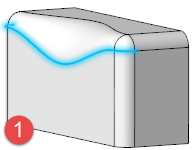
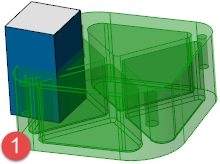
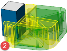
In the following example, the solid body was cut by the blue edges as shown in  . This body has been split into two bodies as shown in
  .
.
In the following example, the solid body was cut by three points as shown in . This body has been split into four bodies as shown in .

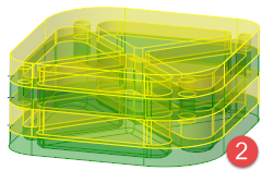
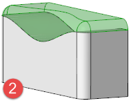
Faces
If the selected cutting entity is a face or several faces, the reference body is cut with respect to the face or faces.
In the following example, the green body was selected for cutting with the blue faces as shown in . This body has been split into several bodies according to the virtual extensions of the blue cutting faces as shown in .
Cut Bodies Options
The following options are available in the Options - Cut Bodies dialog box. ![]() See dialog box.
See dialog box.
Top Toolbar
![]()
![]()
![]()
![]()
![]()
![]()
![]()
![]()
![]()
From left to right, this toolbar displayed at the top of the option dialog box allows you to Apply the current values, to Cancel the current function, to Restore the system defaults and to Restore the defaults that have previously been saved using the Save icon.
Parameters
The following parameters are available after selection of a single point and a cutting direction:
|
Number of cuts |
Allows you to define the number of cuts to be created. |
|
Distance |
Allows you to specify the distance between the cuts. |
Side to keep
The following options allow you to define the side of the cut body to keep:
|
Front side |
Selecting this option allows you to keep the front (outside) parts of the body. |
|
Back side |
Selecting this option allows you to keep the back (inside) parts of the body. |
|
Both sides |
Select this option to keep both parts of the cut body. |
Options
|
Move all sections together |
This option is available if several elements or points have been selected to cut the body. It allows you to adjust the location for all of the sections in one step. |
|
Simplify |
This option attempts to simplify bodies by removing redundant edges and by converting the surfaces underlying each face of the solid and the edges of that face into an analytic form. |
Preview
Preview generation is Automatic if this option is active. Otherwise, click on the Preview button to obtain a preview in the graphic area.
The field at the bottom of the Options panel displays information about missing data, errors or actions.